计算机体系结构cs代写 I218代写 计算机体系结构作业代写
1980I218 Computer ArchitectureReport 3 计算机体系结构cs代写 (1) In the textbook and lecture slides, detailed information in the pipeline registers (IF/ID, ID/EX, EX/MEM, MEM/WB) is not provided. ...
View detailsSearch the whole station
数字电路代写 For this project, students are divided into groups of three (maximum). Each group will apply the techniques introduced in the lecture/tutorial to
For this project, students are divided into groups of three (maximum). Each group will apply the techniques introduced in the lecture/tutorial to complete the design report and present the project.
You are required to design a digital controller with digital inputs and outputs. You should design your own digital controller and state its function.
An example in following for your reference. Your own system should have more inputs and outputs.
An industrial robot that places components on a printed circuit board has 3 failsafe sensors and an emergency shutdown switch. The robotic system will shut down if any of the following conditions occur: 数字电路代写
The following Boolean variables are defined for the system:
A=sensor 1 B=sensor 2 C=sensor 3 D=emergency switch (input)
sensor activated =1 emergency switch pressed =1
F= system shutdown = 1 (output)
Examples of project title:
You are encouraged to think different project title.
Proposal should be submitted in the middle of the module. Proposal should include the followings
The final report should be submitted 1 or 2 weeks before end of the module. No hardware implementation required.
The final report should include the following
Example: Table list individual student work
| Std. Name 1 | Std. Name 2 | Std. Name 3 | |
| Introduction (function of digital controller) | √ | ||
| Diagram to explain the operation of the controller | √ | ||
| List of digital inputs and outputs | √ | ||
| Truth table of the related outputs | √ | ||
| State the not simplified logic function in sum of product form | |||
| Draw the not simplified logic circuit | |||
| Use multiplexer to implement your digital controller | |||
| Use K map to simplify your logic function | |||
| Draw the simplified logic circuit | |||
| Further improvement (e.g. using Arduino micro-processor) |
Report and explain student’s individual works to lecturer and other students. (each student 3-5 minutes)
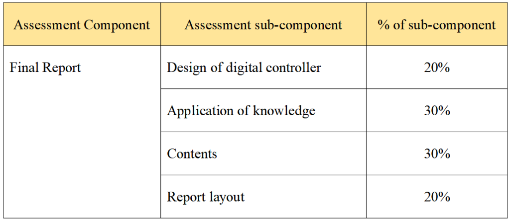
Mark distribution:

更多代写:r语言代写 雅思在家考 英国Accountant网课代考 五段式论文结构 留学文书代写公司 论文写不出来
合作平台:essay代写 论文代写 写手招聘 英国留学生代写

I218 Computer ArchitectureReport 3 计算机体系结构cs代写 (1) In the textbook and lecture slides, detailed information in the pipeline registers (IF/ID, ID/EX, EX/MEM, MEM/WB) is not provided. ...
View details
I218 Computer ArchitectureReport 2 cs计算机体系结构作业代做 (1)How is the instruction “sub $t9, $s4, $s7” translated to a machine instruction code? Answer the rs, rt, and rd fields in binary n...
View details
Economics 426: Problem Set 1 – Robinson Crusoe 经济问题集代做 I. Robin Crusoe is endowed with 112 labor-hours per week. There is a production function for the output of oysters Spring...
View details
Economics 426: Problem Set 8 – Production 经济学生产问题代写 I. Show that if A and B are closed subsets of Rn , then A+B is closed or provide a counter example. (20 pts) II. Show that if A and...
View details