堆栈计算代写 EECS 560代写 Lab代写 c++代写 编译代写
306EECS 560 Lab 4: Index and Postfix Calculation using Stacks 堆栈计算代写 Objective Understand the infix and postfix calculation using stack. Specifications 1. Only addition (“+”), subtraction (...
View detailsSearch the whole station
编解码器代写 Lab Summary In this lab you will use a microcontroller and an audio CODEC to design a 2nd order low pass digital IIR filter. Use this filter to
In this lab you will use a microcontroller and an audio CODEC to design a 2nd order low pass digital IIR filter. Use this filter to remove the noise present in yet another music file. The 2nd order filter can be connected in series (cascaded) to implement 4th and 6th order filters. In the last part of the lab you will evaluate the effectiveness of this technique.
Documents
Lab MCU_CODEC_IIR_Filter_Notes1.pdf
Supplies
The following equipment is required to perform the lab:
Speaker x 1
RCA to BNC adapter x 2
BNC cable x 2
C2000 Peripheral Kit Board x 1
USB cable x 1
Open the project MCU_CODEC_IIR_proj1 provided in the Lab 6 section of the ECE 2050 website.
a two pole IIR filter on the MCU.
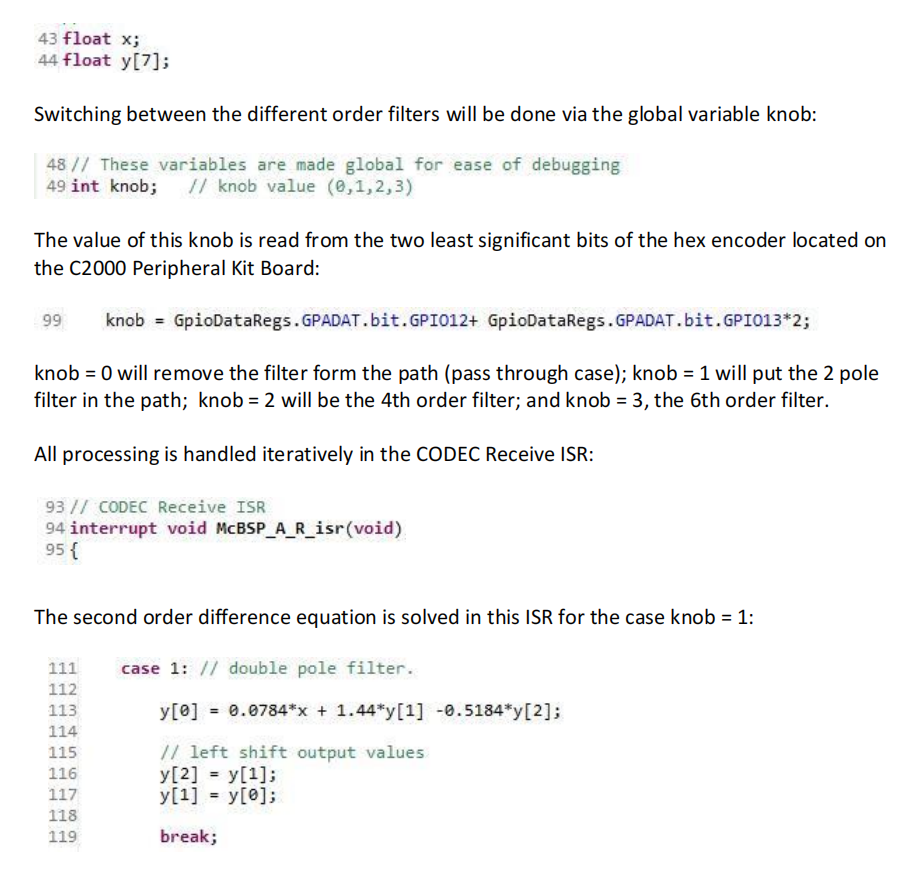
The difference equation of filter is:
y[n] = 0.0784*x[n] + 1.44*y[n‐1] ‐ 0.5184*y[n‐2]
Although the filter is of order N =, two previous iteration values of the input y ( y[n], y[n‐1],y[n‐2] ), are used. Therefore, an array of at least N+ 1 = 3 is required for the y values.. This program is to accommodate up to N=6, as higher order filters are used in subsequent sections of the lab.
1) Set the knob to the value 1. Observe the value of the knob using the debugger
Include the results of all the calculations and plots in your lab report.
2) Derive the Transfer Function H(z) from the difference equation used in Part 1.
3) Plot the pole zero map for this IIR filter in MATLAB. (zplane)
4) Using MATLAB plot the Magnitude Frequency Response of this filter. (freqz)
5) Find the bandwidth of this two pole filter.
Checkpoint 1: Show the Magnitude Frequency response plot to the monitor.
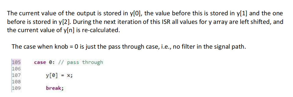
6) Using MATLAB plot the Magnitude Frequency Response of this filter. (freqz)Connect a signal generator to the input of the CODEC and an oscilloscope to the output according to the following diagram.
7) Vary the frequency of sine waves on the Waveform Generator to measure the Magnitude Frequency Response of the filter implemented in the MCU. Complete the Frequency table (located under Lab 6 on the website) and plot your experimental results on top of your theoretical results from step 3). How well do the results match?
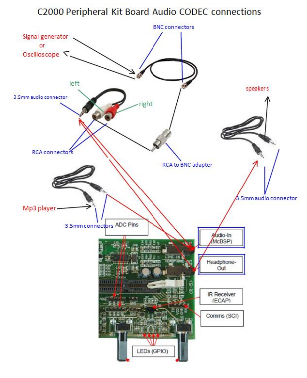
For this section of the lab, you should use the NoisyMusic.wav, which consists of strong high frequency noise superimposed on a well known tune. (located under Lab 6 on the website)
Listen to NoisyMusic.wav music directly on your iPad or other audio device without connecting to the C2000 Peripheral Kit Board. Unpleasent? Yes?
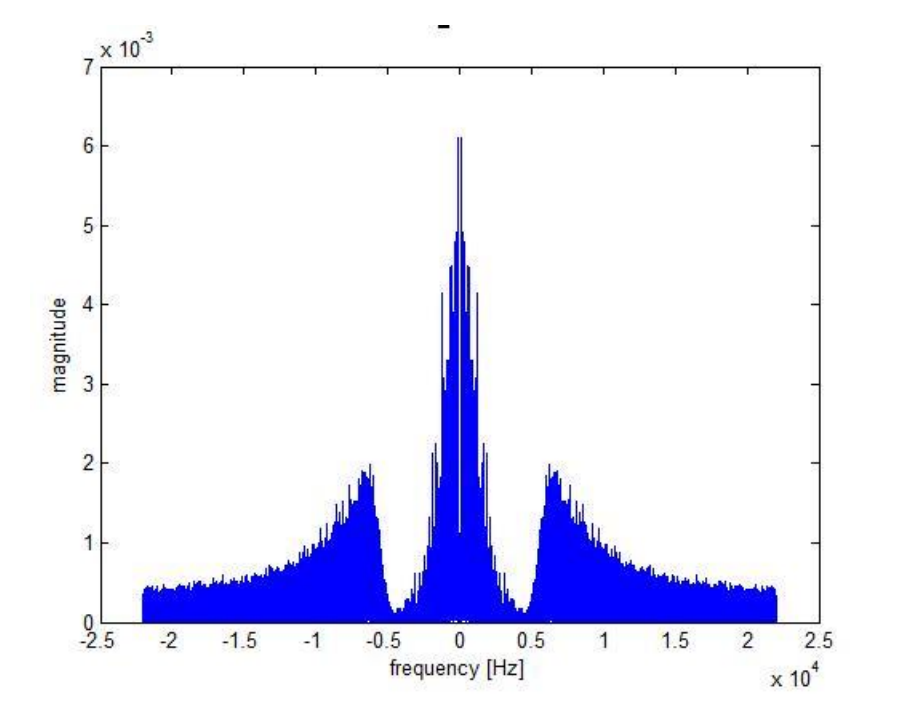
The spectrum of this noisy music is given below:
Note the strong high frequency noise.
Now pass this music through the 2 pole filter.
1) Connect audio‐out from of your iPad to the Audio‐In line of the C2000 Peripheral Kit Board.
2) Connect speakers to the Headphone‐out line. Refer back to the connection diagram.
3) Load and run your program.
4) Play NoisyMusic.wav from your iPad.
5) Switch the C2000 knob between 0 and 1 to hear the filtered and unfiltered music.
Do you hear any difference between the filtered and unfiltered music?
Checkpoint 2: Play both the original and filtered music to the monitor by toggling the knob between 0 and 1.
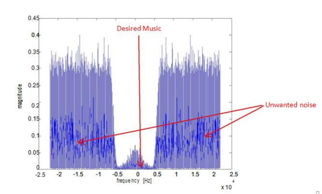
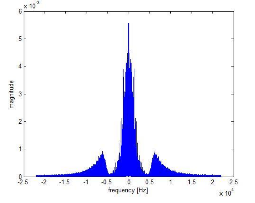
After passing through the 2 pole filter of the spectrum looks like:
Notice how the filter has removed some (but not all) of the noise, increasing the signal-to-noise ratio of the music.
In this procedure you will follow the notes provided to you in the document Lab MCU_CODEC_IIR_Filter_Notes1.pdf to design 4 pole and 6 pole filters by cascading the two pole filter.
1) Design a four pole low pass IIR filter by cascading two 2‐pole filters from Procedure 1 and 2.
2) Adjust the pole value so that the bandwidth is the same as the two pole filter.
3) Make sure the Transfer Function is normalized as explained in the notes.
4) What is the value of the fourth order pole p?
5) What is the value of the normalization constant b0?
6) What is the Transfer (System) Function H(z)?
7) Plot the Magnitude Transfer function in MATLAB, superimposed on the Magnitude Transfer function of the two pole Filter.
8) What is the difference equation corresponding to this Transfer Function?
9) At Insert Point 1 in MCU_CODEC_IIR_proj1.c, add a new case for knob =2.
10) In this case insert the appropriate statements to solve the difference equation for the four pole filter.
11) Play the NoisyMusic.wav file through the CODEC
12) Change the knob’s value between 0, 1, and 2.
13) Describe the difference in music you hear has you change the value of the knob.
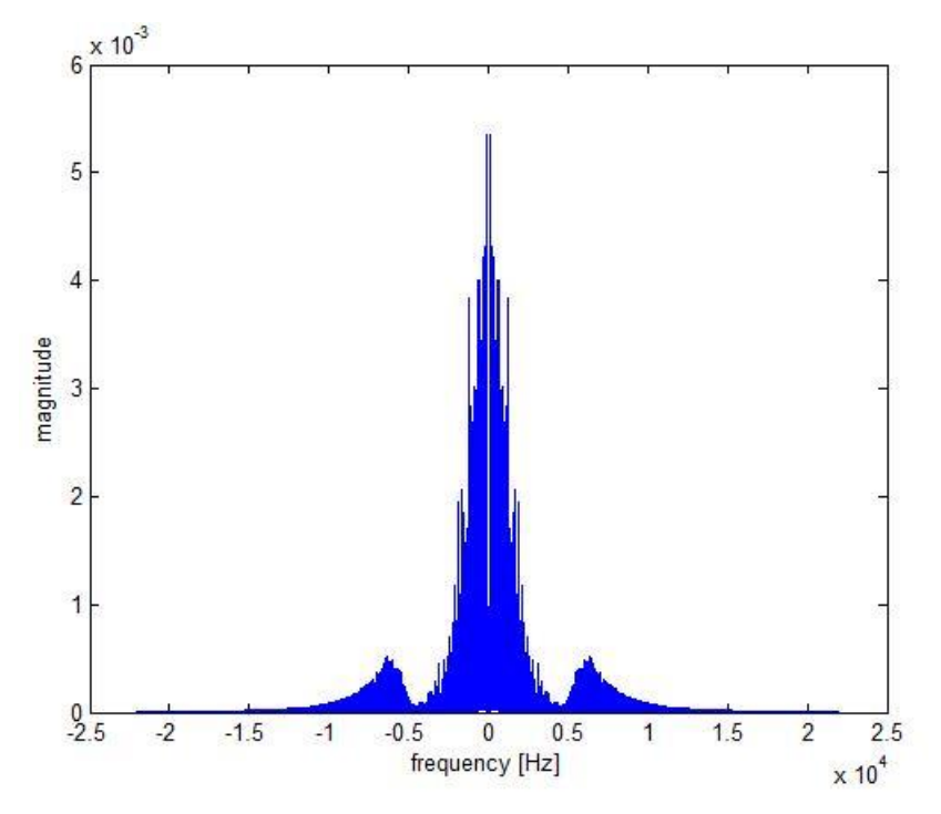
The spectrum of the music after passing through the quad pole filter looks like (you are not asked to generate this spectrum):
Repeat all the steps of Exercise 3 for a 6‐pole IIR filter produced by cascading three 2‐pole filters of Procedures 1 and 2. Make the modifications in the program at Insert Point 1 by adding a new case for knob = 3.
Checkpoint 3: Play the music corresponding to knob = 0, 1, 2 and 3 for the monitor.
The spectrum of the music after passing through the six pole filter looks like (you are not asked to generate this spectrum):
Checkpoint 4: Clean up and show your workbench to the lab monitor.
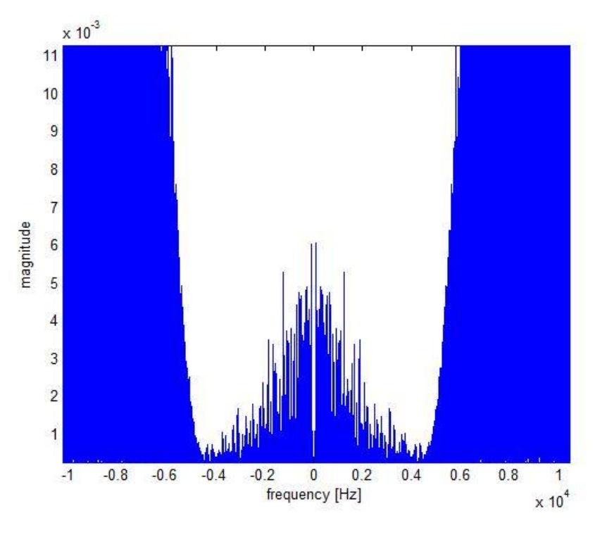
Topic 1: The figure below is a zoomed in view of the spectrum of music with high frequency noise. If you are designing a low pass filter yourself, what cut off frequency would you use for this music? Explain your answer.
Topic 2: Based on the results of the experiments in this lab, is it a good idea to keep on increasing the order of the filters (by cascading filters of the type used in this lab) to get better results? Explain your answer.
Topic 3: Comment on how the magnitude transfer functions of the various filters designed in this lab differ at frequencies lower than the cutoff frequency and above the cutoff frequency. Does cascading filters for higher order filters) improve the quality of the music below cutoff? Does going to higher orders affect the noise above cutoff proportionally? Support your answer.

更多代写:留学生CS代修网课 gre代考一亩三分地 英国留学生法律学课程作业代写 留学生论文作业 留学生学术期刊代写 论文写作指导代写
合作平台:essay代写 论文代写 写手招聘 英国留学生代写

EECS 560 Lab 4: Index and Postfix Calculation using Stacks 堆栈计算代写 Objective Understand the infix and postfix calculation using stack. Specifications 1. Only addition (“+”), subtraction (...
View details